
Six thermal design trends to watch in 2026
In 2026, thermal design is being set less by individual components and more by system‑level constraints: rack power density, advanced packaging, coolant compatibility, material availability, regulation, and the reality of shipping on schedule.
Teams that treat thermal as an optimisation problem under real‑world constraints, rather than a late‑stage verification step, are the ones that will move faster and land stronger designs.
Below are six evidence‑backed areas to watch, and what they mean for thermal teams.
1 - Liquid and hybrid cooling becomes the new baseline
Average data center rack densities continue to rise into the 10–20 kW range, with AI and accelerated compute racks increasingly designed for 50–100 kW and beyond in leading deployments, which is pushing air cooling up against its practical limits. A recent DC Pulse analysis on how rack power impacts PUE in AI data centers shows that while traditional air architectures can remain efficient up to around 20 kW per rack, performance and PUE begin to deteriorate significantly as densities approach 40–80 kW, at which point direct‑to‑chip or immersion liquid cooling becomes the most viable path to maintain efficiency and reliability.
What changes in 2026? It is not just adoption, but expectation as new high‑density projects are increasingly scoped assuming that some form of liquid cooling will be available, with air reserved for lower‑power subsystems, comfort cooling, or as a secondary path. For a deeper view of this shift, JetCool’s overview of power density trends and the shift to liquid cooling describes how AI and HPC racks with heat loads greater than 100 kW per rack are accelerating liquid cooling adoption, while broader rack‑density explainers show how 10–20 kW per rack is becoming a common design point.
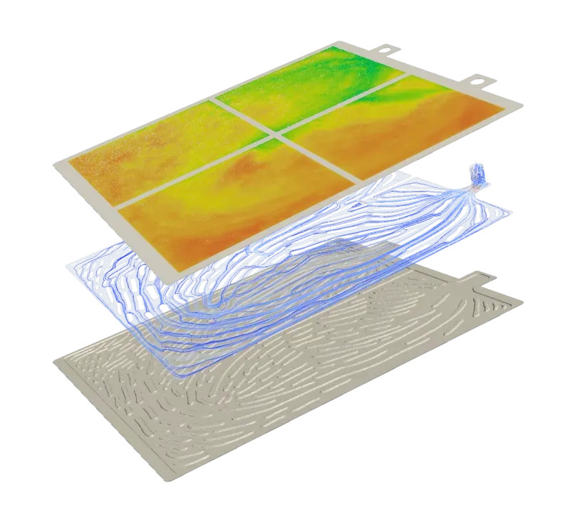
Implication for thermal teams: The design space expands dramatically, from manifold strategies and CDU sizing to coolant chemistries, materials compatibility, and serviceability. The bottleneck shifts to iteration speed: teams that embed optimisation early (coolant temperatures, flow distribution, cold plate topology, and air‑liquid interaction) will converge on robust architectures faster and avoid late‑stage, layout‑driven compromises.
2 - Advanced semiconductor packaging pushes thermal “inside the package”
The shift from monolithic 2D devices to 2.5D and 3D integrations chiplets on interposers, HBM stacks, and vertically integrated dies means that thermal is increasingly part of package architecture rather than a problem solved with a bigger heat sink at the end.
Next‑generation AI and HPC packages with multi‑die integrations are being announced at package powers in the hundreds of watts up to around a kilowatt, which forces package engineers to co‑optimise power delivery, mechanical stack‑up, and thermal escape paths from the earliest design stages.
As a result, the traditional split between “package design” and “system‑level thermal design” is eroding. Package‑level choices bump pattern, underfill, substrate design, TIM1/TIM1.5 selection, embedded heat spreaders directly dictate how much flexibility remains at the module, board, and rack levels, especially once liquid cooling and advanced materials are introduced.
Implication for thermal teams: More projects will have the “right” answer inside the package, not only on top of it. Thermal engineers will increasingly influence integration strategies—how heat is spread within the package, how localised liquid or vapor chambers are used, which TIM stack‑ups are viable—alongside mechanical and electrical constraints.
3 - Thermal materials 2.0 and premium TIMs move from “nice to have” to strategic
Thermal interface materials (TIMs) and advanced heat spreaders are shifting from commodity consumables to performance multipliers. Independent forecasts such as the IDTechEx
Global Thermal Interface Materials Market report project robust growth over the next decade, highlighting data centers, EVs, power electronics, and advanced computing as key demand drivers, with high‑performance TIMs capturing a growing share of value compared with conventional greases and pads.
Other analyses, including Reports and Data’s thermal interface materials market overview and Delvens’ TIMs market forecast, underline that computers and data centers currently represent the largest application segment, while automotive and power electronics are among the fastest‑growing users of advanced TIMs and gap fillers.
At the same time, materials such as liquid metals, highly conductive gap fillers, and engineered graphite‑based spreaders offer step‑change improvements in effective thermal conductivity and reliability, but introduce new constraints around assembly, long‑term stability, and regulation.
These materials decisions now appear much earlier in design reviews, because the combination of topology, TIM stack‑up, coolant, and operating envelope often determines whether a concept is viable without major redesign. Although they were never treated in isolation, with more options, comes more opportunities but also complexity when evaluation the best combination.
Implication for thermal teams: Material choices are no longer “secondary decisions” but a large part of the primary design space. The winning workflows will treat geometry, materials, and operating conditions as a coupled optimisation problem, balacing cost, manufacturability, reliability, and regulatory compliance against raw thermal performance.
4 - Electrification and automotive electronics intensify multi‑domain thermal design
Electrification keeps pushing thermal challenges beyond single components. Latest‑generation EV platforms combine high‑power batteries, inverters, on‑board chargers, and increasingly compute‑heavy ECUs and domain controllers, often connected through multiple liquid loops that also interact with cabin comfort and, in some cases, waste‑heat recovery.
At the same time, increasingly automated and assisted‑driving functions turn the vehicle into a multi‑domain compute platform: perception stacks, sensor fusion pipelines, and centralised domain controllers add concentrated heat loads alongside batteries and power electronics, all competing for thermal headroom in tightly packaged environments.
Recent market and technical coverage of ADAS and autonomous driving hardware highlights how high‑performance SoCs, radar, LiDAR, and camera modules now require dedicated thermal strategies to maintain reliability and algorithm performance under real‑world conditions.
In this environment, thermal engineering is not just about keeping a single device below a limit; it spans functional safety, packaging, mechanical robustness, cost‑down pressures, and software‑driven control strategies under aggressive development timelines. Designs must balance peak performance, fast charging, component life, autonomous and ADAS compute availability, and customer comfort, all within constrained packaging envelopes.
Implication for thermal teams: Repeatable, referenceable architectures matter. Teams that can start from validated multi‑loop concepts covering both powertrain and automated‑driving compute, explore design variants efficiently, and converge early on manufacturable solutions will be better positioned to handle platform reuse, regulatory shifts, and late‑stage requirement changes without major rework.
5 - Regulation, sustainability, and reliability become first‑order design drivers
Thermal decisions are increasingly constrained by regulatory and sustainability requirements, not just physics and cost. In Europe, ongoing work to restrict certain PFAS chemistries under REACH is a clear example: coolants, seals, coatings, and materials used in thermal systems may need to change over time, and designs must be resilient to such shifts. Eurovent’s summary of the PFAS restriction under REACH explains how a broad class of PFAS substances including some refrigerants and processing aids could face restrictions, with details being refined as ECHA’s scientific committees progress their evaluations.
Complementary updates, such as the revised PFAS restriction dossier discussed by industry groups and laboratories, emphasise the potential for phased bans and time‑limited exemptions, reinforcing that material choices made today may face regulatory pressure within a typical product lifetime.
At the same time, data centers and other energy‑intensive infrastructure face mounting pressure to improve efficiency, enable heat reuse, and document their environmental footprint as part of broader ESG and sustainability frameworks.
As the external environment ultimately impacts what can be achieved, expect to see more emphasis on not only companies but also industries where they are best positioned to deliver their products. Evaluating economies that favour and support a design and innovation approach will be seen as a safer haven for tech and fast-growth companies to use as a playground.
Implication for thermal teams: “Best thermal performance” is no longer enough. The target becomes optimal performance within constraints that include manufacturability, supply chain resilience, regulatory compliance, and lifecycle impacts such as refrigerant choice and heat‑reuse potential.
6 - High‑density compute across industries drives convergent thermal innovation
As many are aware, high‑density compute is not unique to data centers and is a cross‑industry reality than ever before. Cloud and AI infrastructure are visible examples, with many operators now designing for 50–100 kW racks and exploring liquid cooling to keep PUE under control, as detailed in analyses of rack power and PUE along with vendor case studies on direct‑to‑chip liquid cooling. Yet similar thermal pressures exist in aerospace and defense avionics, mission payloads, and compute‑heavy automotive ECUs, all of which must handle more heat in less volume under stringent reliability expectations.
Data centers often attract attention because of their scale, how they impact businesses and everyday users and energy use, which amplifies the impact of each cooling decision.
But aerospace, defense, and automotive teams face many of the same trade‑offs which is “how to cool densely integrated electronics, how to preserve serviceability and qualification paths, and how to leave headroom for future power increases.”
This convergence is leading to shared expertise and sector-sharing insights around liquid loops, advanced materials, modular cooling blocks, and reuse of validated reference architectures across different industries.
Implication for thermal teams: Expect more board‑level and program‑level scrutiny of thermal architecture decisions, regardless of sector. Thermal is increasingly viewed as a cross‑program capability: lessons and solutions from data center, automotive, or A&D projects will inform each other, and teams that can generalise their best practices will move faster across multiple product lines. There are opportunities to look at industry-adjacent applications and ask the question “what does that mean for our market?”
So what does this translate into for thermal design teams in 2026 and the short term?
Thermal engineering is becoming a discovery‑and‑optimisation problem under real‑world constraints, not a late‑stage “trial‑and‑error” validation exercise. The most practical positioning for optimisation‑driven thermal workflows is not “more design variants,” but a change in how the conventional design workflow process is utilised.
Four key areas to look out for are:
- Discovery: Find better thermal directions earlier in the design cycle, while architecture is still flexible. This creates substantial efficiencies in downstream project time due to reducing the impact of bias early on in the design process and finding designs that align with your project needs.
- Optimisation: Quantify trade‑offs across geometry, materials, cooling strategies, and operating conditions instead of relying solely on worst‑case checks. By translating constraints into tangible impacts from your product, you’re able to optimise in the areas where they matter most to key thermal outcomes.
- Viability: Ensure solutions remain manufacturable, serviceable, and compliant as materials, regulations, and power targets evolve. However this should be balanced by assessing opportunities incorporating new and constantly evolving abilities in various manufacturing techniques such as additive manufacturing. Lastly, coupling this with the external environment. For example how it aligns within each facet of a PESTEL analysis
- Workflow fit: Protect schedules by integrating thermal exploration into existing processes, reducing late changes and preserving downstream engineering bandwidth. Arguably some would say it expands the project timeline but due to the benefits and project-specific applicable thermal design learnings , there is opportunities for post discovery phases can be reduced, and condolences, proving an over-all faster project timeline. Thermal design teams that build this mindset into their workflows will be better placed to deliver reliable, scalable systems in 2026 and beyond.

.png)